This is a job that can be done with common tools and in less than an
hour.
** Remember, safety first!**
Step 1: Remove the ignition key.
Step 2: Remove cowling, then all spark plug
wires from plugs, then all
spark plugs.
Step 3: Make sure gear housing is in Neutral.
Step 4: Tilt motor to full up position and
engage the tilt lock lever.
Step 5: Disconnect the pitot hose
(speedometer) and remove propeller,
(makes it easier to do next step).
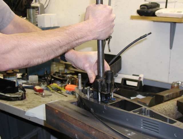
 |
Photo
1 - Step 5 - Removing the prop
using a 2 x 4.
* Click on thumbnails for large
photos. |
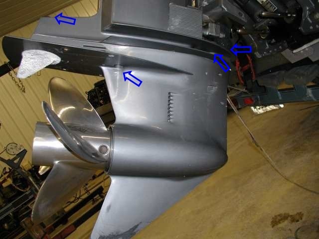
Step 6: If you have a trim tab, mark it
and the housing so you can put it
back in the same location for reinstallation (grease
pencil works well).
If you have a flat anode plate this is not needed.
Step 7: Remove the plastic cap at the
rear edge of driveshaft housing so you can remove the bolt holding the trim tab.
Step 8: With trim tab removed, remove bolt
inside trim tab cavity.
Step 9: Remove two lock nuts/washers from
bottom middle of anti-cavitation plate.
Step 10: Remove locknut and washer or plate
from front gear housing stud.
Step 11: Loosen the 2 side locknuts.
Both nuts must be loosened sufficiently before either one can be removed
and the housing will be loose at this point.
 |
Photo 2
- Steps 7 to 11 -
Indicates the nuts/bolts to be removed.
|
Step 12: Pull gear housing as far away
from drive shaft housing as you can then
remove the loosened nuts.
( Be careful...it's now free, so don't let
it fall!)
**Note:
As you remove the gear housing from drive shaft housing, watch for the
possibility of the water supply tube to stay in water pump housing as you
remove the gear housing. IF it does, go ahead and remove gear housing then
remove the water tube from water pump housing and re-install it back into
drive shaft housing and into powerhead grommet.
(You will have to push it back up into rubber grommet). It should stay at
this point, (you will need a flashlight to see up to grommet.)
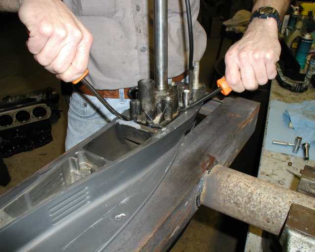
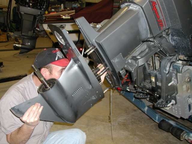
 |
Photo 3
- Steps 12 to 16
Removing the water pump housing.
|
Step 13: Mount the housing
on something that will hold it in a sturdy upright
position.
Step 14: Now we're ready to remove the water
pump housing.
To do this, remove the 3 nuts/washers and 1 bolt.
Step 15: Remove the water guide tube
and slide the rubber slinger up the driveshaft
to remove it.
Step 16: Using 2 small pry bars
(medium size screwdrivers will work), lift the
waterpump housing up and slide it up and off of driveshaft.
(If the impeller goes up with it, watch for the
key.)
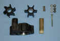 |
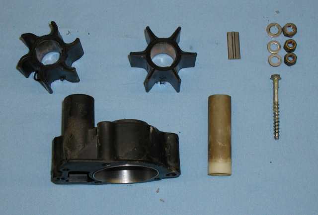
Photo
4 - Top row shows the old
impeller, new impeller, key, nuts &
washers and screw.
Second row shows the WP housing &
guide tube. |
Step 17: Remove the
impeller the same way as you did the housing by sliding
it up and off the driveshaft (may have to use a pry bar if it is stuck in
place). Remove the key.
Step 18: Inspect pump housing for cracks and
the stainless insert for wear. If it
has any it will also need to be repaired or replaced. Also check the
face plate (located under the impeller) for signs of
wear.
(If you remove the plate you will need to replace
all the gaskets.)
Step 19: If all is ok, (and/or you you have
repaired/replaced them), then it's time to
start reassembly.
Step 20: If removed, slide
the gasket/face plate down the driveshaft into position
then gasket onto studs, then the key (make sure it is in flat of
driveshaft, using a small amount of grease will help hold the key in
place.)
Step 21: Now slide the new impeller down onto
the key. (Make sure the key and keyway in
impeller hub align together.)
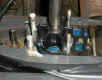 |
Photo 5
- New Impeller in place and ready to go back
together. |
Step 22: Put a VERY light coat of grease on
water pump housing insert,
(just enough to help impeller slide into housing.)
Step 23: Slide housing down to the impeller and
studs, now turn driveshaft
CLOCKWISE (viewed from top), with one hand as you
push water pump housing down over impeller
& studs.
 |
Photo 6 -
Installing the housing...push down as turning
driveshaft clockwise. |
Step 24: Put nuts/washers and bolt back on
and tighten. (DO NOT OVER TIGHTEN as you can
damage housing. Torque spec: 50 in. lbs. on nuts, 35 in.
lbs. on bolt.)
Step 25: Reinstall the rubber sling washer
& guide tube. Also make sure that
the bolt for trim tab/anode plate is still in place.
Step 26: Put small amount of grease on drive
shaft splines, (keep it off the top, do sides
only) and also put small amount on shift shaft (same as drive shaft,
sides only).
Step 27: Shift control box/motor into forward
gear. Next, slide prop back onto prop
shaft (no nut). Take pliers and as you turn prop counter-clockwise
turn shift shaft clockwise until in full forward gear.
(Do not turn prop clockwise).
Step 28: We're now ready
to install gear housing back onto drive shaft housing,
so position gear housing so the drive shaft protrudes into the housing and
you have to make sure the supply tube from power head starts into the
guide tube on pump.
Then, as the drive shaft gets up to the power head
you will need to turn counter-clockwise to align splines of drive shaft
and crankshaft.
Also, you must check that the shift shaft from gear housing to shaft in
driveshaft housing slide together properly.
Once everything is aligned the gear housing should fit back up against the
driveshaft housing.
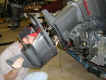 |
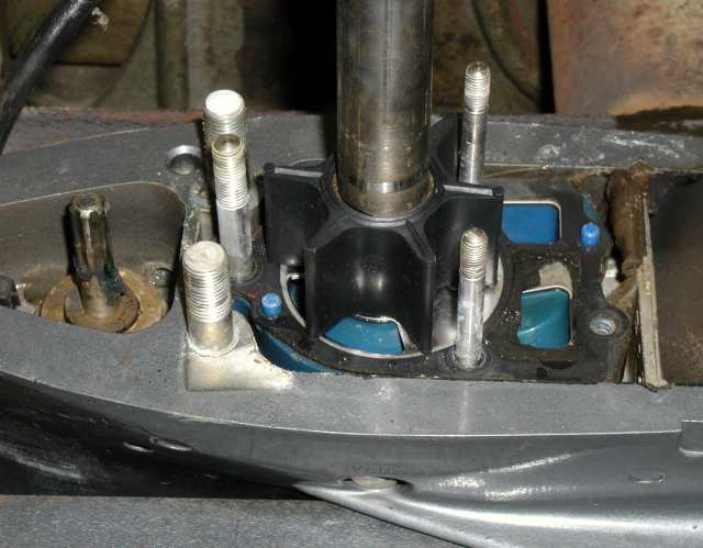
Photo 7 -
Re-installing the gear housing. |
Step 29: Install the 2 side locknuts
(gear housing will have to be away from driveshaft
housing a small amount for clearance for the nuts to fit over the
studs). Once both nuts are in place, push gear housing back tight
against and snug up the 2 nuts.
Step 30: Check shifting operation by
putting control box/motor back into neutral.
Prop should turn freely in both directions. If not, have the shift
shaft off and you must redo Step 28.
Step 31: Once all checks out ok, install the
2 locknuts in back under the cavitation
plate. Then the 1 bolt in trim tab cavity. Then the
locknut/washer on front stud. Now tighten all 6 nuts/bolts to 55
ft.lbs, then install trim tab/anode plate. Reconnect pitot hose.
Step 32: Slide prop back off, grease
propshaft splines, then reinstall.
Thrust washer, prop, washers & nut. Torque to 55
ft. lbs. (piece of wood - 2x4 works good while tightening nut).
|
Photo 8 -
Re-installing the prop. |
Last Step: Reinstall spark
plugs and wires.
|