First step in this project, just as in any other
is .....Study & Analyze it before and as you are taking it
apart so you'll know how to put it back together.
With that said, let's get started..........
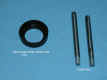 |
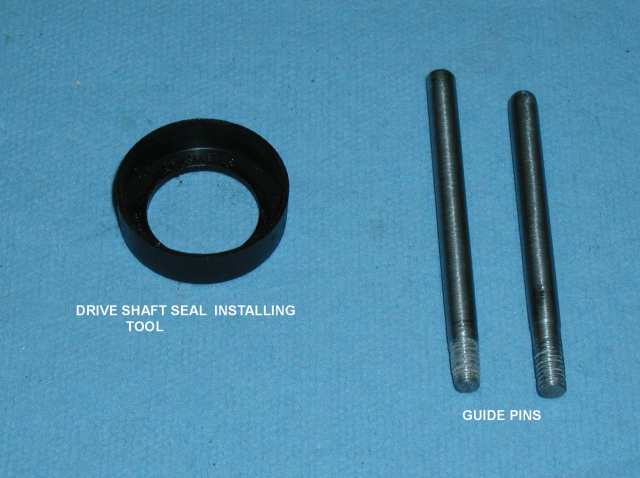
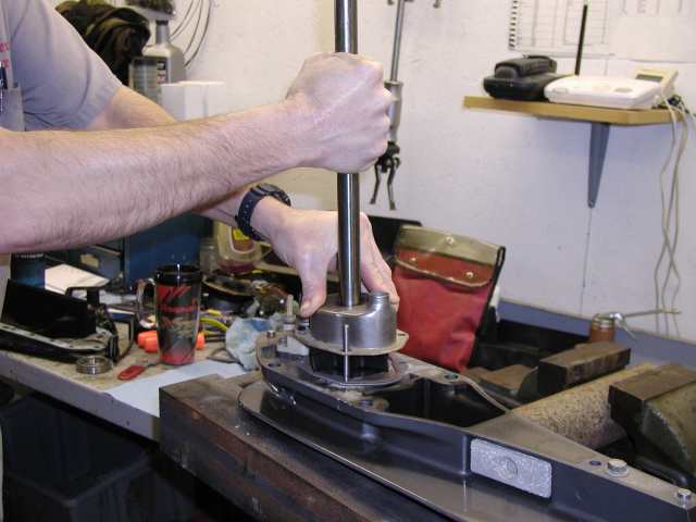
Photo #1 -
"Special tools needed to aid in doing the job
easier and correctly.
|
Step 1: Remove ignition key and spark
plug wires. IF you are going to use a helper method it will also help if
you remove the spark plugs. (It it's an Opti I wouldn't). You will
understand why the spark plug removal helps later.
Step 2: Put motor in NEUTRAL.
Step 3: Tilt motor to full up and engage
the lock to hold motor up.
Step 4: Remove propeller.
Step 5: Disconnect the pitot hose
(speedometer) at the coupler.
Step 6: If you have a trim tab, mark it for
a reference to know its location at reassembly (grease pencil works
well). If you only have an anode plate you can skip this step.
Step 7: Remove plastic cap for access to
trim tab/anode bolt. Then remove the bolt (it's down in the
hole). Then remove the bolt in the cavity above the tab.
Step 8: Loosen the side locknuts, (2 on
each side) as shown in Photo #2.
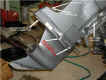 |
Photo #2 - Showing
side locknuts to remove. |
Step 9: After all 4 have been
loosened sufficiently, pull the gear housing away from drive shaft
housing until it's against the 4 nuts. Then remove the loosened
nuts. ( * Gear housing will be free so don't let it fall!)
**Note:
As you remove the gear housing from drive shaft housing, watch for the
possibility of the water supply tube to stay in water pump housing as
you remove the gear housing. IF it does, go ahead and remove gear
housing then remove the water tube from water pump housing and
re-install it back into drive shaft housing and into powerhead grommet.
(You will have to push it back up into rubber grommet). It should stay
at this point, (you will need a flashlight to see up to grommet.)
Step 10: Slide it out of drive shaft
housing and place it in/on a suitable holding device or bench vice to
hold it with drive shaft in a vertical position, (drive shaft pointing
straight up.
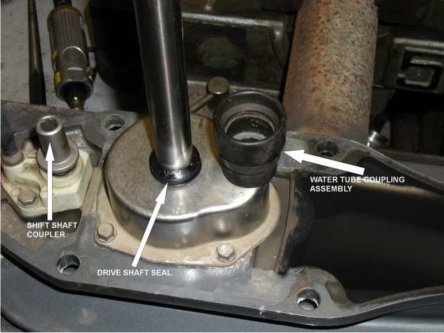
Step 11: Time for disassembly of the water
pump. Remove the rubber water seal (slide it up the driveshaft)
and the water tube coupling assembly (it may have stayed on the supply
tube in drive shaft housing) if it's not on water pump housing.
Then remove the 4 bolts in water pump housing. (Metric bolts).
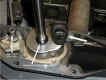 |
Photo #3 - Removing
bolts in water pump housing. |
Step 12: Lift water pump housing up
and off. (May have to use 2 screwdrivers to lightly pry up if it's
stuck). Watch as you lift the housing...the impeller may stay in housing
(it's ok if it does), but make sure the key stays put (don't lose it.)
Step 13: If the impeller stayed put, go
ahead and remove it. (If it's stuck use your screwdrivers to
lightly pry it up). Be careful not to damage the face plate.
Once the impeller and key are off, remove the face plate and gaskets
(2), one
on each side of plate.
Step 14: Time to inspect the water pump
housing & face plate, also the water tube coupling assembly.
Check them for wear or any other type of damage,
(grooves or heat damage). The coupling assembly has 2 O-rings
inside of it.
Check them for cuts, nicks, etc., and replace if needed.
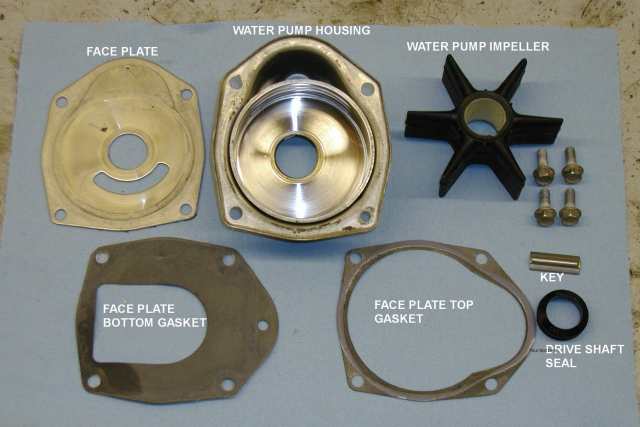
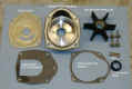 |
Photo #4 - Showing
new parts needed. |
Step 15: Clean gasket surface areas
of gear housing, both sides of face plate and water pump housing.
Step 16: Time to start reassembly.....Place
NEW face plate base gasket on gear housing. The face plate, then NEW
top gasket. *Make sure the 4 bolt holes all align; (if they don't, you
have something upside down) as shown in photo #5.
 |
Photo #5 - Starting
reassembly and alignment. |
Step 17: Install the key (use a small
amount of grease to hold key in place).
It goes on the flat area of drive shaft. Then slide the NEW
impeller down and
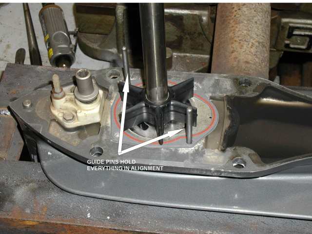
over the key. (Make sure it all aligns.)
Next step is much easier if you have the alignment pins to install as
shown in
Photo #1. (You can make them; they are (in this case anyway), 6mm bolts
without heads).
Step 18: Put a VERY light coat of
grease in the water pump housing insert area.
Then slide housing down shaft to impeller and align with pins if you
have them.
Step 19: With one hand, turn driveshaft CLOCKWISE
(as you look down from
top) and with other hand push down housing onto impeller. Keep
turning drive shaft until the housing is all the way down. **
Without the pins you will have a
big problem keeping things aligned and not screwing up the top gasket.
Shows this in Photo #6.
 |
Photo #6 -
Installing housing onto impeller. |
Step 20: Install the 4 bolts finger
tight and then evenly tighten them with final
torque of 60 in. lbs. Then install the water pump rubber
seal. (They have a special tool for this too, it comes with seal
kits and water pump repair kits.)
VERY IMPORTANT
to get this seal installed properly to prevent air from being drawn into
pump resulting in overheating. If no tool is available, push it
down until it has a height of 0.350 in. +/- 0.30 in. (that's about
11/32")
Step 21: Install the water tube coupling
after lightly greasing 0-rings. Then grease the splines on drive
shaft and shift shaft (* keep grease off top end - only do sides).
Step 22: Time to install gear housing back
onto motor. Have two methods for
this.....
#1 Without helper #2 With helper....we'll cover method #1
first......
Method #1
Step 23: Put control box/motor in forward
gear....then turn propshaft COUNTER- CLOCKWISE as you rotate the
shift shaft CLOCKWISE (shift shaft will only turn less than 1/4
turn), until you have it in forward gear.
You will feel it go into gear and propshaft will become very hard to
turn, so stop....it's in gear.
Step 24: Time to install gear housing, so
slide your prop back on temporarily.
Step 25: Slide gear housing back up into
drive shaft housing as when you removed it. As you get it up near
the top you will need to feed the pitot hose through the hole in
driveshaft housing and as you get it closer you will need to rotate the
prop COUNTER-CLOCKWISE to align splines on drive shaft to the
crankshaft. After it aligns, you stop turning prop and make sure
the shift shaft aligns and slides together. Once all is aligned
push drive shaft up tight.
Method #2
Step 23: Time to install gear housing, so take
it and slide it back up into drive shaft housing as you did to remove
it.
Step 24: As you are near to getting it back
up into place you need to feed pitot hose through hole in drive shaft
housing. Then as it gets even close you have
to have your
helper turn over the powerhead by rotating the flywheel a small amount
to align splines. Next make sure the shift shafts align together.
When all is aligned, slide it up tight.
Next step for both methods:
Start the 4 side locknuts (you can stop holding gear housing in place
after you get one nut on a few turns).
Step 25/26: Snug up at least one nut
on each side to hold it up tight in place.
Then check shift operation. With Method #1, it's already in gear,
so shift to
NEUTRAL. Prop should spin free in both directions. IF NOT, you
must redo
Step 24. With Method #2 - Temporarily
install prop and have helper turn it
COUNTER-CLOCKWISE as you shift into Forward gear, it should go into gear
and stop turning. IF NOT, redo step 24.
** Never shift into forward or reverse
without having shafts moving!!
Can cause damage!!
Step 27: Everything works right.....so
finish tightening 4 side locknuts.
(Torque spec is 55 ft. lbs.) Then install bolt back under
cavitation plate in trim tab recessed cavity - torque to 45 ft.
lbs. Then install trim tab or anode plate and torque bolt to 40
ft. lbs. Put plastic cap back in access hole.
Step 28: Pull prop off if it was on, grease
prop shaft and reinstall prop and all hardware, torque to 55 ft. lb.
Step 29: Reinstall plug wires (plugs first
if you used Method #2).
Final Note:
If you used Method #2, the reason to remove the plugs is so you can turn
the motor over easier without building compression.
Well......it's time to find out how your job
performs.....TEST RUN TIME!!
Any questions?? Sherman |